
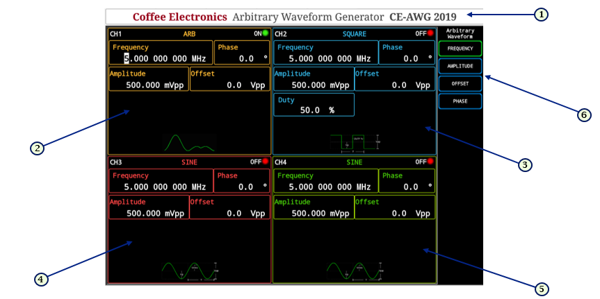
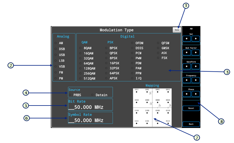
Arbitrary Waveform Generator

Arbitrary Waveform Generator Control Panel Overview

System Panel
| System Panel | Button | Function | Button | Function |
|---|---|---|---|---|
 |
 |
Resets the Arbitrary Waveform Generator to default settings. |  |
some text here |
 |
some text here |  |
some text here | |
 |
some text here |  |
some text here |
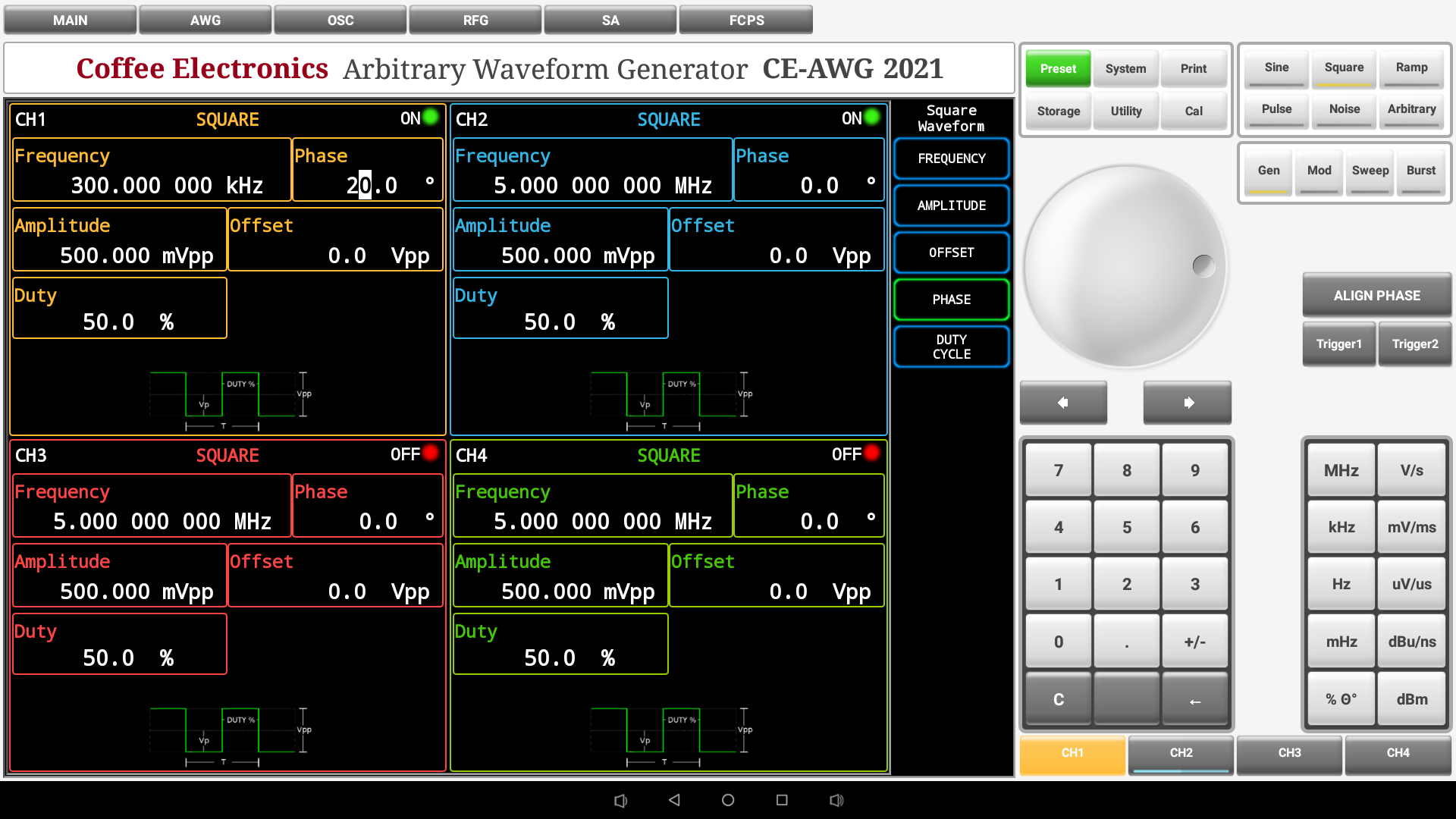
Waveform Panel
| Waveform Panel | Button | Function | Button | Function |
|---|---|---|---|---|
 |
 |
It puts a sine wave on the active channel, displays the sine wave menu to configure its parameters. |  |
It puts a pulse wave on the active channel, displays the pulse wave menu to configure its parameters. |
 |
It puts a square wave on the active channel, displays the square wave menu to configure its parameters. |  |
It puts a noise signal on the active channel, displays the noise signal menu to configure its parameters. | |
 |
It puts a ramp wave on the active channel, displays the ramp wave menu to configure its parameters. |  |
It puts an arbitrary waveform on the active channel, displays the arbitrary waveform menu to configure its parameters. |
Mode Panel
| Mode Panel | Button | Function | Button | Function |
|---|---|---|---|---|
 |
 |
It changes to the generator screen (Image 7) where the parameters and waveform are configured |  > > |
Switches to the modulation screen (Image 8) where the modulation parameters are configured |
 |
Switches to the sweep screen where the sweep parameters are configured |  |
Switches to the burst screen where the burst parameters are configured |
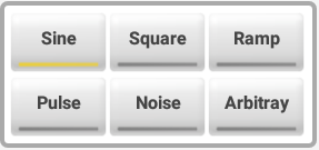
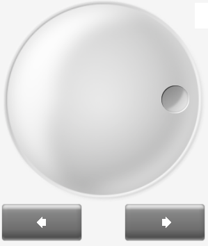
Universal Knob and Arrows
| Universal Knob and Arrows | Button | Function | Button | Function |
|---|---|---|---|---|
 |
 |
Increase or decrease any active numeric value on screen. |  |
Both have the same function than the universal knob, Increase or decrease any active numeric value on screen. |
Numeric Keypad
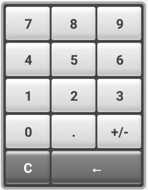 |
Enter the numerical value in the active configuration parameter on the screen. | |||
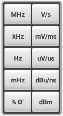
Units Keypad
| Units Keypad | Button | Function | Button | Function |
|---|---|---|---|---|
 |
 |
Gives the unit of megahertz to the entered numeric value. (Only if the parameter is frequency). |  |
Sets a unit of microvolts if the active parameter receives voltage values or unit of microseconds if the active parameter corresponds to unit of time. |
 |
Sets a unit of Volts if the active parameter receives voltage values or unit of seconds if the active parameter corresponds to unit of time. |  |
Gives the unit of millihertz to the entered numeric value. (Only if the parameter is frequency). | |
 |
Gives the unit of kilohertz to the entered numeric value. (Only if the parameter is frequency). |  |
Place as a percentage unit if the active parameter is in percentage, or degrees if the active parameter is expressed in degrees. | |
 |
Sets a unit of millivolts if the active parameter receives voltage values or unit of milliseconds if the active parameter corresponds to unit of time. |  |
Returns the decibel-millivolt unit to the entered numeric value. | |
 |
Gives the unit of Hertz to the entered numeric value. (Only if the parameter is frequency). |
Channel Buttons
| Channel buttons | Button | Function | Button | Function |
|---|---|---|---|---|
 |
 |
Turns on, off and / or selects channel 1 wave output. |  |
Turns on, off and / or selects channel 2 wave output. |
 |
Turns on, off and / or selects channel 3 wave output. |  |
Turns on, off and / or selects channel 4 wave output. |
Arbitrary Waveform Generator Screen View
 |
|
 |
|
Sweep Screen
Burst Screen
Arbitrary Waveform Generator Functions
To Set Channels
Press ![]() ,
, ![]() ,
,
![]() or
or ![]() buttons to switch the selected channel and the output state. The state of the channel is
displayed with a led
buttons to switch the selected channel and the output state. The state of the channel is
displayed with a led ![]() /
/ ![]() on the upper part of each channel, when a channel is selected the button is
highlighted with the color of that channel
on the upper part of each channel, when a channel is selected the button is
highlighted with the color of that channel ![]() , in that case the parameters of that channel can be selected and
edited.
, in that case the parameters of that channel can be selected and
edited.
To Set Waveform output
The following section describes how to set and output one of the seven available waveforms: sine, square, ramp, pulse, noise, arbitrary, and DC signal.
Set Sine Signal
 |
|
Detailed Instructions
- For setting the Frequency, press the frequency
 button in the sine wave parameters submenu, then the cursor will be activated in the frequency box for
the sine wave in the selected channel, the value can be modified through the numeric keypad, or through the knob, the
unit is entered with the units keyboard and the decimal to edit can be changed with the arrows below the knob.
button in the sine wave parameters submenu, then the cursor will be activated in the frequency box for
the sine wave in the selected channel, the value can be modified through the numeric keypad, or through the knob, the
unit is entered with the units keyboard and the decimal to edit can be changed with the arrows below the knob. - For setting the Amplitude, press the amplitude
 button in the sine wave parameters submenu, then the cursor will be activated in the amplitude box for
the sine wave in the selected channel, the value can be modified through the numeric keypad, or through the knob, the
unit is entered with the units keyboard and the decimal to edit can be changed with the arrows below the knob.
button in the sine wave parameters submenu, then the cursor will be activated in the amplitude box for
the sine wave in the selected channel, the value can be modified through the numeric keypad, or through the knob, the
unit is entered with the units keyboard and the decimal to edit can be changed with the arrows below the knob. - For setting the Offset, press the offset
 button in the sine wave parameters submenu, then the cursor
will be activated in the offset box for the sine wave in the selected channel, the value can be modified through the
numeric keypad, or through the knob, the unit is entered with the units keyboard and the decimal to edit can be changed
with the arrows below the knob.
button in the sine wave parameters submenu, then the cursor
will be activated in the offset box for the sine wave in the selected channel, the value can be modified through the
numeric keypad, or through the knob, the unit is entered with the units keyboard and the decimal to edit can be changed
with the arrows below the knob. - For setting the Phase, press the phase
 button in the sine wave parameters submenu, then the cursor
will be activated in the phase box for the sine wave in the selected channel, the value can be modified through the
numeric keypad, or through the knob, the unit is entered with the units keyboard and the decimal to edit can be changed
with the arrows below the knob.
button in the sine wave parameters submenu, then the cursor
will be activated in the phase box for the sine wave in the selected channel, the value can be modified through the
numeric keypad, or through the knob, the unit is entered with the units keyboard and the decimal to edit can be changed
with the arrows below the knob.
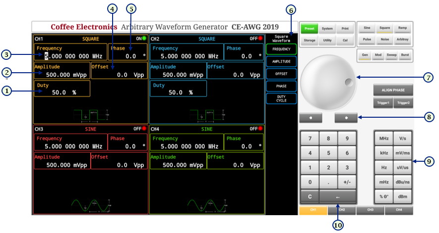
Set Square Signal
 |
|
Detailed Instructions
- For setting the Duty, press the duty
 button in the square wave parameters submenu, then the cursor
will be activated in the duty box for the square wave in the selected channel, the value can be modified through the
numeric keypad, or through the knob, the unit is entered with the units keyboard and the decimal to edit can be changed
with the arrows below the knob.
button in the square wave parameters submenu, then the cursor
will be activated in the duty box for the square wave in the selected channel, the value can be modified through the
numeric keypad, or through the knob, the unit is entered with the units keyboard and the decimal to edit can be changed
with the arrows below the knob. - For setting the Frequency, press the frequency button in the square wave parameters submenu, then the cursor will be activated in the frequency box for
the square wave in the selected channel, the value can be modified through the numeric keypad, or through the knob, the
unit is entered with the units keyboard and the decimal to edit can be changed with the arrows below the knob.
- For setting the Amplitude, press the amplitude button in the square wave parameters submenu, then the cursor will be activated in the amplitude box for
the square wave in the selected channel, the value can be modified through the numeric keypad, or through the knob, the
unit is entered with the units keyboard and the decimal to edit can be changed with the arrows below the knob.
- For setting the Offset, press the offset button in the square wave parameters submenu, then the cursor
will be activated in the offset box for the square wave in the selected channel, the value can be modified through the
numeric keypad, or through the knob, the unit is entered with the units keyboard and the decimal to edit can be changed
with the arrows below the knob.
- For setting the Phase, press the phase button in the square wave parameters submenu, then the cursor
will be activated in the phase box for the square wave in the selected channel, the value can be modified through the
numeric keypad, or through the knob, the unit is entered with the units keyboard and the decimal to edit can be changed
with the arrows below the knob.
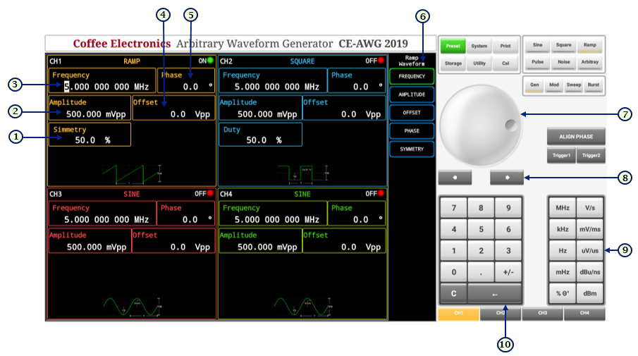
Set Ramp Signal
 |
|
Detailed Instructions
- For setting the Symmetry, press the symmetry
 button in the ramp wave parameters submenu, then the cursor
will be activated in the symmetry box for the ramp wave in the selected channel, the value can be modified through the
numeric keypad, or through the knob, the unit is entered with the units keyboard and the decimal to edit can be changed
with the arrows below the knob.
button in the ramp wave parameters submenu, then the cursor
will be activated in the symmetry box for the ramp wave in the selected channel, the value can be modified through the
numeric keypad, or through the knob, the unit is entered with the units keyboard and the decimal to edit can be changed
with the arrows below the knob. - For setting the Frequency, press the frequency button in the ramp wave parameters submenu, then the cursor will be activated in the frequency box for
the ramp wave in the selected channel, the value can be modified through the numeric keypad, or through the knob, the
unit is entered with the units keyboard and the decimal to edit can be changed with the arrows below the knob
- For setting the Amplitude, press the amplitude button in the ramp wave parameters submenu, then the cursor will be activated in the amplitude box for
the ramp wave in the selected channel, the value can be modified through the numeric keypad, or through the knob, the
unit is entered with the units keyboard and the decimal to edit can be changed with the arrows below the knob.
- For setting the Offset, press the offset button in the ramp wave parameters submenu, then the cursor
will be activated in the offset box for the ramp wave in the selected channel, the value can be modified through the
numeric keypad, or through the knob, the unit is entered with the units keyboard and the decimal to edit can be changed
with the arrows below the knob.
- For setting the Phase, press the phase button in the ramp wave parameters submenu, then the cursor
will be activated in the phase box for the ramp wave in the selected channel, the value can be modified through the
numeric keypad, or through the knob, the unit is entered with the units keyboard and the decimal to edit can be changed
with the arrows below the knob.
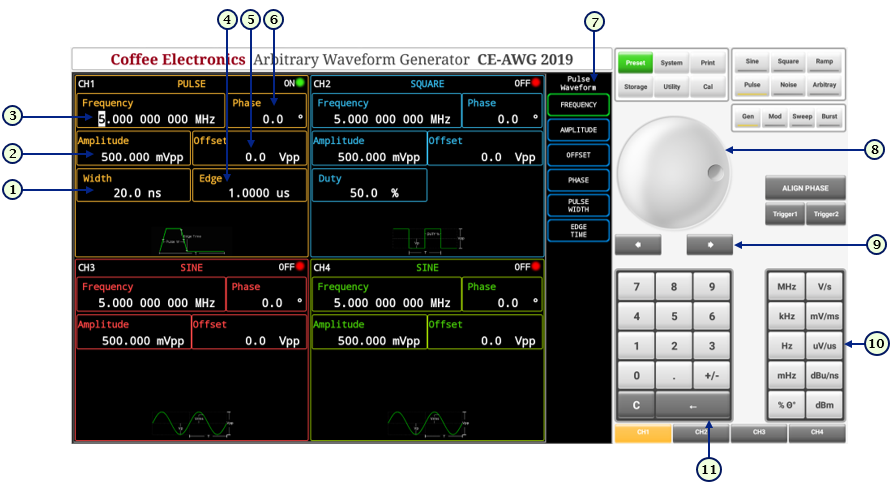
Set Pulse Signal
 |
|
Detailed Instructions
- For setting the Width, press the width
 button in the pulse wave parameters submenu, then the cursor
will be activated in the width box for the pulse wave in the selected channel, the value can be modified through the
numeric keypad, or through the knob, the unit is entered with the units keyboard and the decimal to edit can be changed
with the arrows below the knob.
button in the pulse wave parameters submenu, then the cursor
will be activated in the width box for the pulse wave in the selected channel, the value can be modified through the
numeric keypad, or through the knob, the unit is entered with the units keyboard and the decimal to edit can be changed
with the arrows below the knob. - For setting the Frequency, press the frequency button in the pulse wave parameters submenu, then the cursor will be activated in the frequency box for
the pulse wave in the selected channel, the value can be modified through the numeric keypad, or through the knob, the
unit is entered with the units keyboard and the decimal to edit can be changed with the arrows below the knob.
- For setting the Amplitude, press the amplitude button in the pulse wave parameters submenu, then the cursor will be activated in the amplitude box for
the pulse wave in the selected channel, the value can be modified through the numeric keypad, or through the knob, the
unit is entered with the units keyboard and the decimal to edit can be changed with the arrows below the knob.
- For setting the Edge time, press the edge time
 button in the pulse wave parameters submenu, then the cursor will be activated in the edge time box for
the pulse wave in the selected channel, the value can be modified through the numeric keypad, or through the knob, the
unit is entered with the units keyboard and the decimal to edit can be changed with the arrows below the knob.
button in the pulse wave parameters submenu, then the cursor will be activated in the edge time box for
the pulse wave in the selected channel, the value can be modified through the numeric keypad, or through the knob, the
unit is entered with the units keyboard and the decimal to edit can be changed with the arrows below the knob. - For setting the Offset, press the offset button in the pulse wave parameters submenu, then the cursor
will be activated in the offset box for the pulse wave in the selected channel, the value can be modified through the
numeric keypad, or through the knob, the unit is entered with the units keyboard and the decimal to edit can be changed
with the arrows below the knob.
- For setting the Phase, press the phase button in the pulse wave parameters submenu, then the cursor
will be activated in the phase box for the pulse wave in the selected channel, the value can be modified through the
numeric keypad, or through the knob, the unit is entered with the units keyboard and the decimal to edit can be changed
with the arrows below the knob.
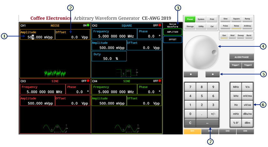
Set Noise Signal
 |
|
Detailed Instructions
- For setting the Amplitude, press the amplitude button in the noise wave parameters submenu, then the cursor will be activated in the amplitude box for
the noise wave in the selected channel, the value can be modified through the numeric keypad, or through the knob, the
unit is entered with the units keyboard and the decimal to edit can be changed with the arrows below the knob.
- For setting the Offset, press the offset button in the noise wave parameters submenu, then the cursor
will be activated in the offset box for the noise wave in the selected channel, the value can be modified through the
numeric keypad, or through the knob, the unit is entered with the units keyboard and the decimal to edit can be changed
with the arrows below the knob.
Set Arbitrary Signal
 |
|
Detailed Instructions
- For setting the Frequency, press the frequency button in the arbitrary wave parameters submenu, then the cursor will be activated in the frequency box
for the arbitrary wave in the selected channel, the value can be modified through the numeric keypad, or through the
knob, the unit is entered with the units keyboard and the decimal to edit can be changed with the arrows below the
knob.
- For setting the Amplitude, press the amplitude button in the arbitrary wave parameters submenu, then the cursor will be activated in the amplitude box
for the arbitrary wave in the selected channel, the value can be modified through the numeric keypad, or through the
knob, the unit is entered with the units keyboard and the decimal to edit can be changed with the arrows below the
knob.
- For setting the Offset, press the offset button in the arbitrary wave parameters submenu, then the
cursor will be activated in the offset box for the arbitrary wave in the selected channel, the value can be modified
through the numeric keypad, or through the knob, the unit is entered with the units keyboard and the decimal to edit can
be changed with the arrows below the knob.
- For setting the Phase, press the phase button in the arbitrary wave parameters submenu, then the
cursor will be activated in the phase box for the arbitrary wave in the selected channel, the value can be modified
through the numeric keypad, or through the knob, the unit is entered with the units keyboard and the decimal to edit can
be changed with the arrows below the knob.